Instalacija
Citerm | Heating Systems
Instalacija
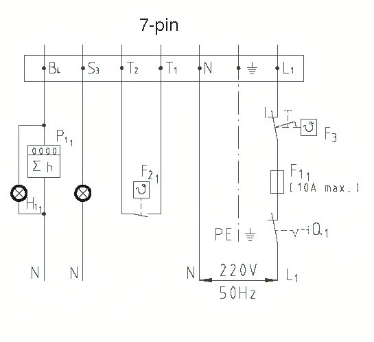
Connecting 7-th pin connector to power supply
- B4 – can be connected to hour meter
- S3 – signal for malfunction
- T1 & T2 – room thermostat
- F3 – Boiler thermostat
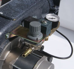
Compressed air inlet
- Connect a compressed air line to the pressure regulator
- Be shore that air pressure is more then 1,5 bar
- The primary airflow should be set using the pressure regulator according to the required burner output. The information given in the diagram (page 5) can be used as guide values
- Higher-viscosity fuels require higher air pressures
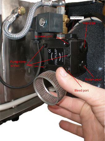
Oil pump
The oil pumps serve as delivery units, pumping oil into the burner tank. The atomization of the oil is not dependent on the oil pressure.
Do not increase oil pressure under any circumstances!
Connect 4 meters of oil pipe between return port and storage tank.
Connect 1 meter of oil pipe between inlet port and FAG filter 1”.
Connect 3 meters of oil pipe between FAG filter and storage tank.
CAUTION: It is recommended that fuel be at a temperature of 5 degrees Celsius or higher when it enters the pump. At a temperature below 5 degrees Celsius oil becomes more viscous and difficult to pump. Supply of the burner tank may be reduced, resulting in nuisance shutdowns.
The storage tank should be no closer than 1,5m and no farther then 10m from the burner. If the thank is lower than the boiler and is more then 5m away from burner, then external pump must be used.
At the bottom of the supply tank manual valve must be installed (for water and sludge separation)
WARNING: Never install suction line at the bottom of the supply tank! Suction line must be fitted at 20cm higher from bottom.
Supply lines
Read this section carefully before installing any supply lines. Since a suction line leak is nearly impossible to find, take your time to assure all connections are leak-free during installation. Supply lines and fittings are furnished by the installer. With the vacuum gauge mounted on the pump vacuum port, the gauge will indicate any suction line restriction, including a dirty filter. All piping should be protected from possible damage and be rigidly fastened in place in workmanlike manner.
NOTE: Care must be exercised to ensure leak-free connections.
Flue connection
Important condition for perfect operation of the furnace is a correctly dimensioned flue. Dimensioning is effected in accordance with DIN 4705 in consideration of DIN 18160 and based on the boiler and burner outputs. The effective flue height is counted from burner level. Select a flue design which minimizes the danger of condensation or of a cold flue inner wall.
For exact adjustment and stabilization of the flue draught we recommend the installation of a draught limiter.
By this means:
- any draught fluctuations are equalized
- moisture in the flue is largely excluded
- stoppage losses are reduced
Connection pieces should be introduced into the flue with a gradient of 30° or 45° viewed in flow direction. It is best to provide exhaust gas pipes with thermal insulation.
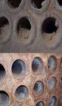
Exhaust gas thermometer
For exhaust gas temperature monitoring the heating system should be equipped with an exhaust gas thermometer. The higher the exhaust gas temperature, the greater the exhaust gas loss. Rising exhaust gas temperatures indicate increasing deposits of ash inside of combustion chamber, that will reduce the degree of combustion efficiency. In the event of an increasing exhaust gas temperature have the heating installation cleaned (see picture ) .